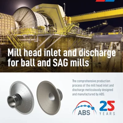
The comprehensive production process of the mill head inlet and discharge for ball and SAG mills, meticulously designed and manufactured by ABS.
Mill head inlet and discharge manufacturing process for ball and SAG mills
The project
This “Mill head inlet and discharge” project is just one of the many that ABS has designed and manufactured for the cement and mining industries. However, it can serve as a valuable summary of a process in which, as can be seen, every detail is meticulously attended to so that the piece reaches the customer in the required conditions.
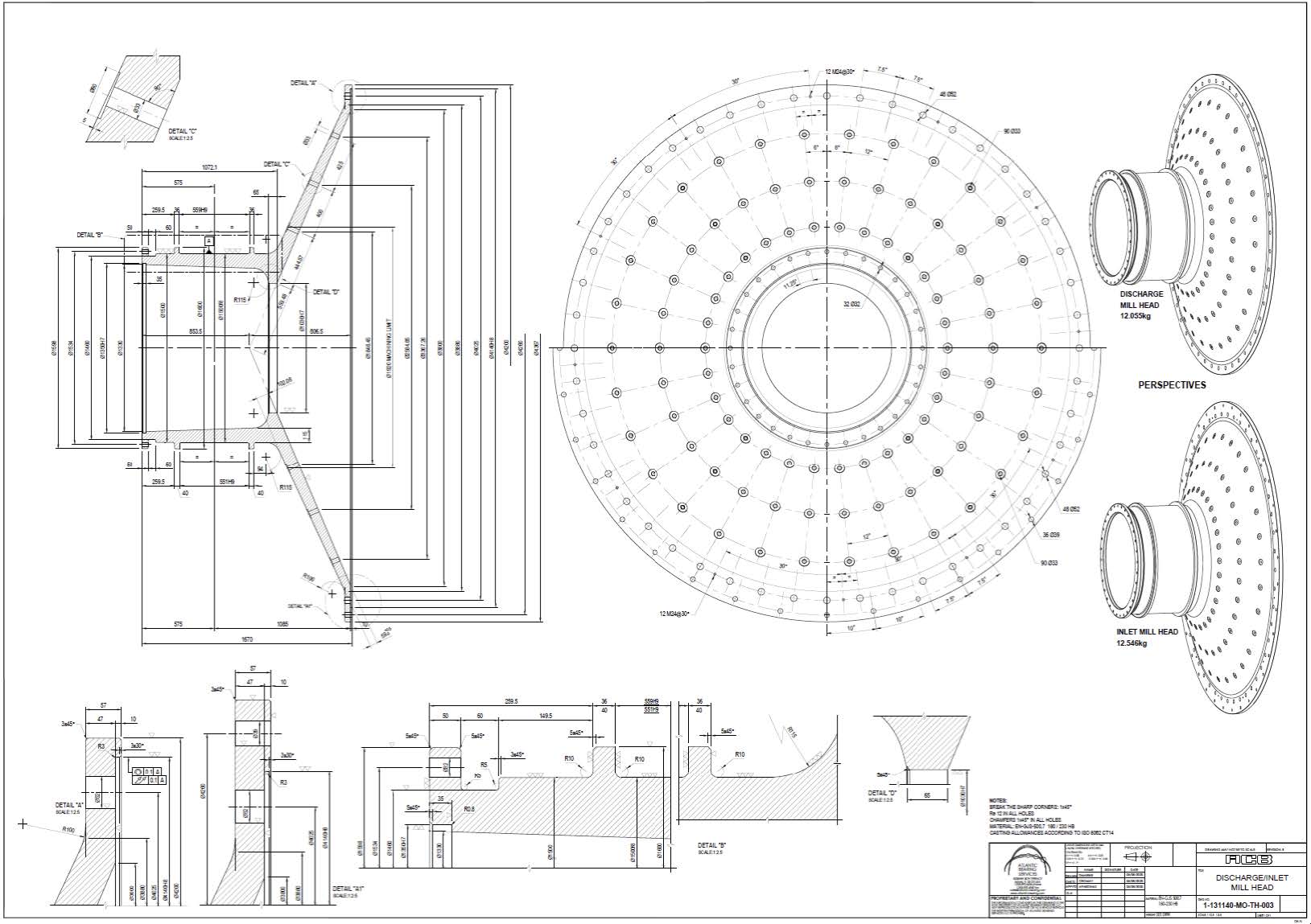
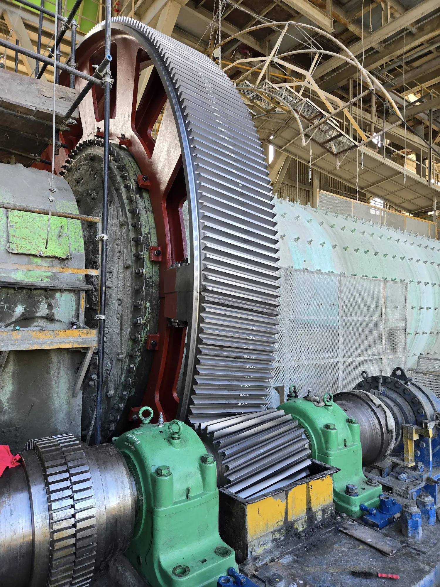
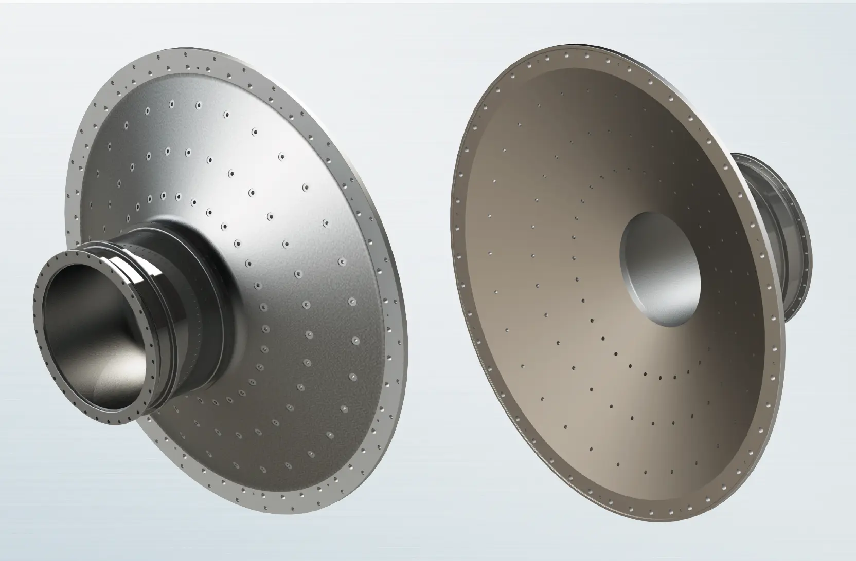
Mill Head inlet and discharge – Solids
In this phase of the project, the focus is on designing and optimizing the inlet and discharge sections of the Mill Head to efficiently handle solid materials. This involves ensuring a smooth flow of solids into and out of the mill, minimizing blockages, and reducing wear and tear on the components. The goal is to enhance the overall performance and durability of the mill by addressing the specific challenges associated with solid material processing.
Mill head inlet and discharge – Materials
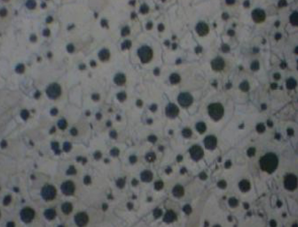
NODULAR IRON is a type of cast iron characterized by its high ductility and strength, due to the presence of graphite in the form of spherical nodules within its structure. This property gives it a unique combination of mechanical strength and energy absorption capacity, making it ideal for structural applications and components subjected to dynamic loads.
- EN-GJS- 400- 18: This material stands out for its excellent ductility and elongation capacity, making it particularly useful in applications where plastic deformation is a critical concern. It has a minimum tensile strength of 400 MPa and an elongation of 18%.
- EN-GJS- 450- 10: With a minimum tensile strength of 450 MPa and an elongation of 10%, this type of nodular iron offers a balance between strength and ductility. It is suitable for components that require higher strength without significantly compromising deformation capacity.
- EN-GJS- 500- 7: This material has a minimum tensile strength of 500 MPa and an elongation of 7%. It is ideal for applications that demand high strength and where the loads are predominantly static.
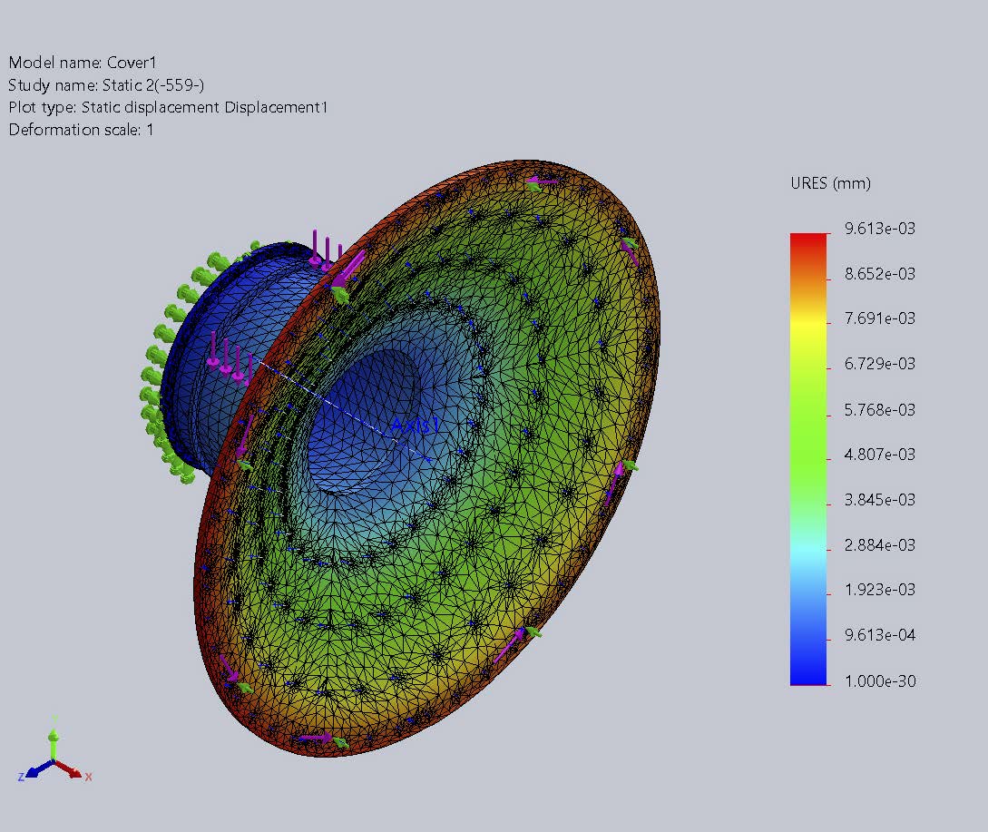
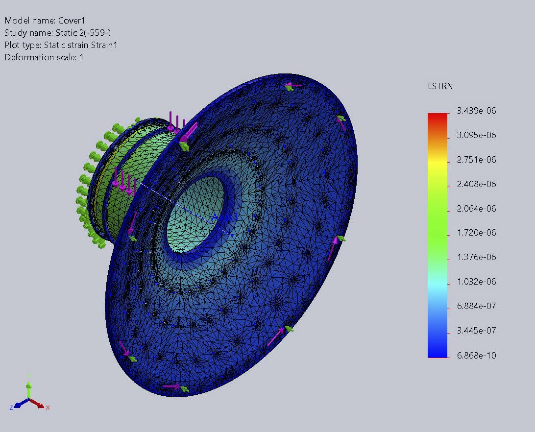
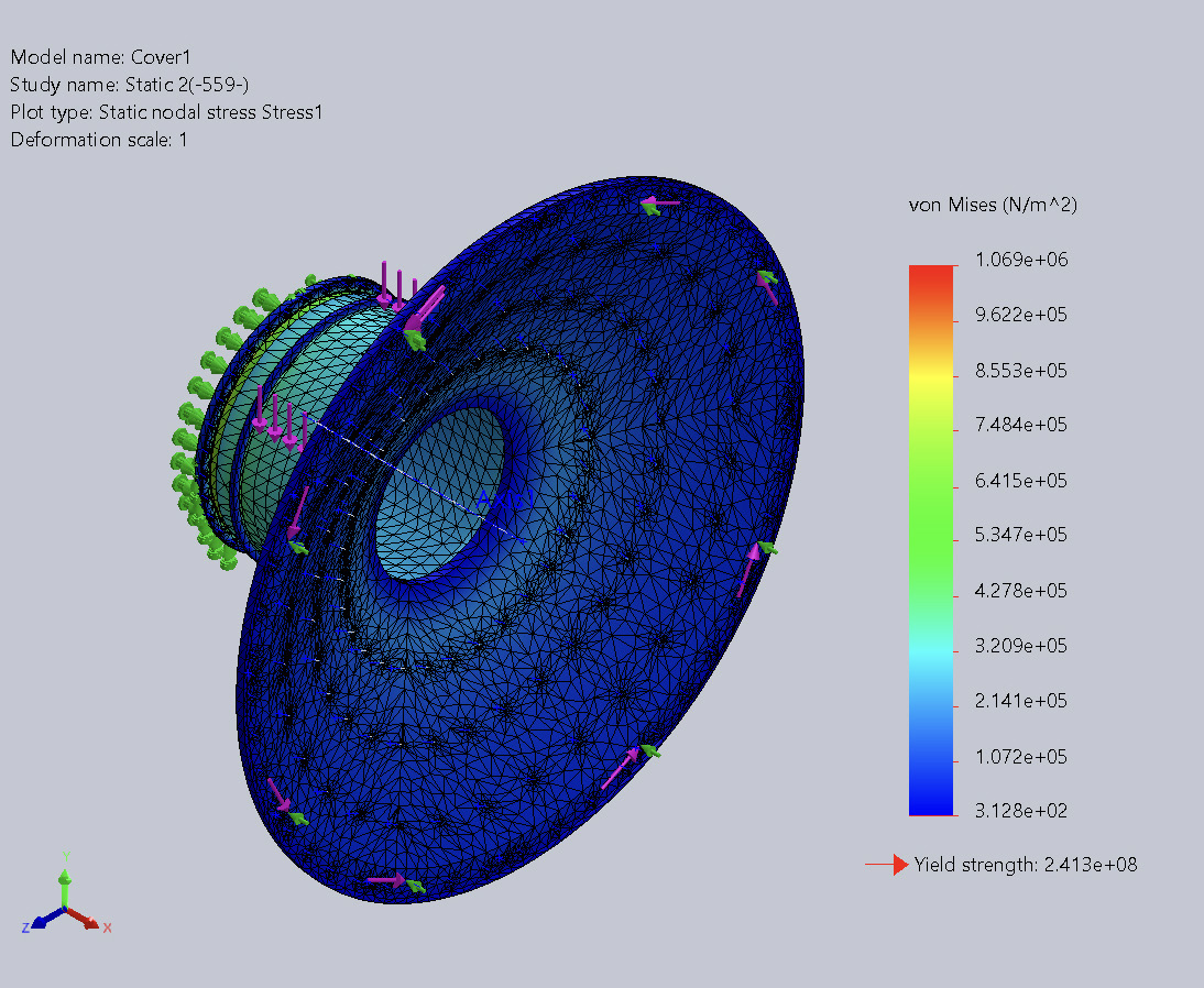
FEM Analysis
Finite Element Method (FEM) analysis is a crucial technique in structural engineering, used to evaluate and optimize the design of complex mechanical components. In the context of a Mill Head for a cement mill, this analysis allows us to determine how the structure will respond under various loads and operational conditions.
The focus is on calculating the displacements, stresses, and deformations that the mill head will experience during operation. By segmenting the Mill Head into a finite element mesh, it is possible to simulate the material behavior and the acting forces with high precision. This process is essential to identify potential failure points, optimize the design for improved durability and efficiency, and ensure that the component meets the required safety standards.
Displacement analysis is one of the critical stages, as it allows us to visualize how the structure deforms and how these deformations can affect the performance and integrity of the mill. This knowledge is vital for engineers when designing more robust and efficient components, extending the equipment’s lifespan and reducing long-term maintenance costs.
Manufacturing of Lost Foam Casting (LFC) Molds
In this phase of the project, the focus is on manufacturing casting molds using the Lost Foam Casting (LFC) technique. This method involves creating a foam model that is coated with a refractory layer and then placed in sand. During casting, the molten metal vaporizes the foam and takes its place, forming a high-precision piece with a smooth surface finish. This process is ideal for producing complex components with fine details and reduces the need for subsequent machining, optimizing both the quality of the final product and production efficiency.
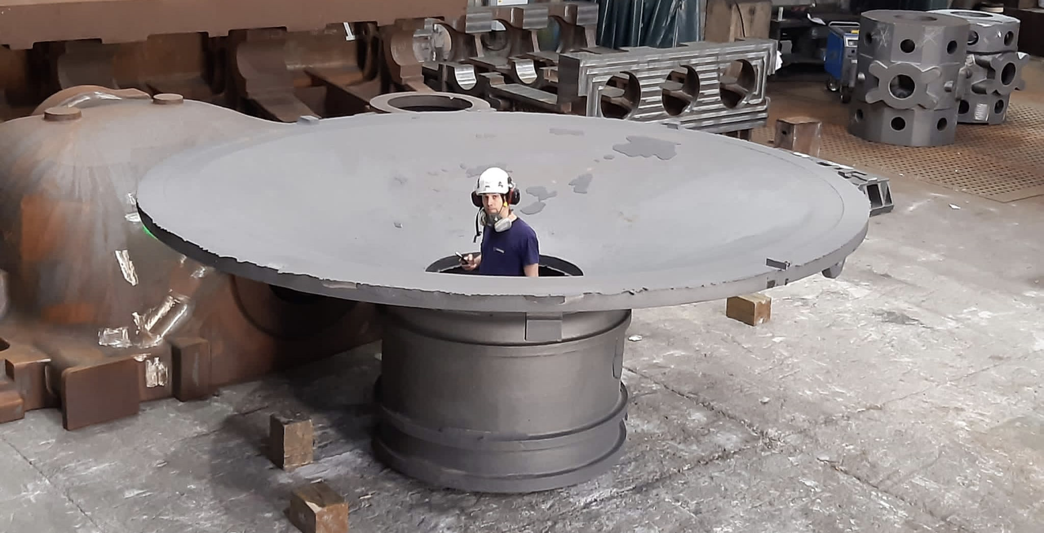
Casting Output
In this phase, the focus is on the final stage of the casting process where the molded component is extracted from the mold. This involves carefully removing the sand and refractory coating to reveal the cast part. The component is then inspected for quality, including checking for defects and ensuring it meets the specified dimensions and surface finish. This step is crucial to ensure that the casting is ready for any further processing or direct use in its intended application.
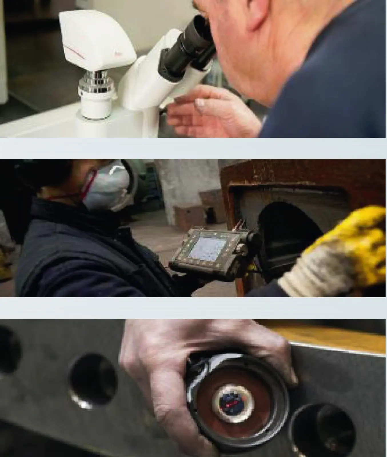
Quality control
Quality control is paramount to ensure that the Mill Head meets all design specifications and industry standards. This involves a series of rigorous inspections and tests, including:
- Dimensional Verification: Ensuring that all dimensions of the Mill Head conform to the design drawings and tolerances.
- Material Testing: Verifying the chemical composition and mechanical properties of the materials used.
- Non-Destructive Testing (NDT): Using techniques such as ultrasonic testing, radiography, and dye penetrant inspection to detect any internal or surface defects.
- Surface Finish Inspection: Checking the surface finish to ensure it meets the required smoothness and quality standards.
- Load Testing: Simulating operational conditions to verify the Mill Head’s performance under expected loads and stresses.
- Microstructure and Metallographic Analysis: Examining the material’s microstructure and physical structure to assess quality and identify defects.
- Stress and Maximum Stress Analysis: Calculating and analyzing stresses to ensure the Mill Head can withstand operational conditions and identifying maximum stress points.
- Hardness Analysis: Measuring the hardness of the material to verify it meets necessary standards.
These quality control measures are essential to ensure the reliability, safety, and longevity of the Mill Head in its operational environment.
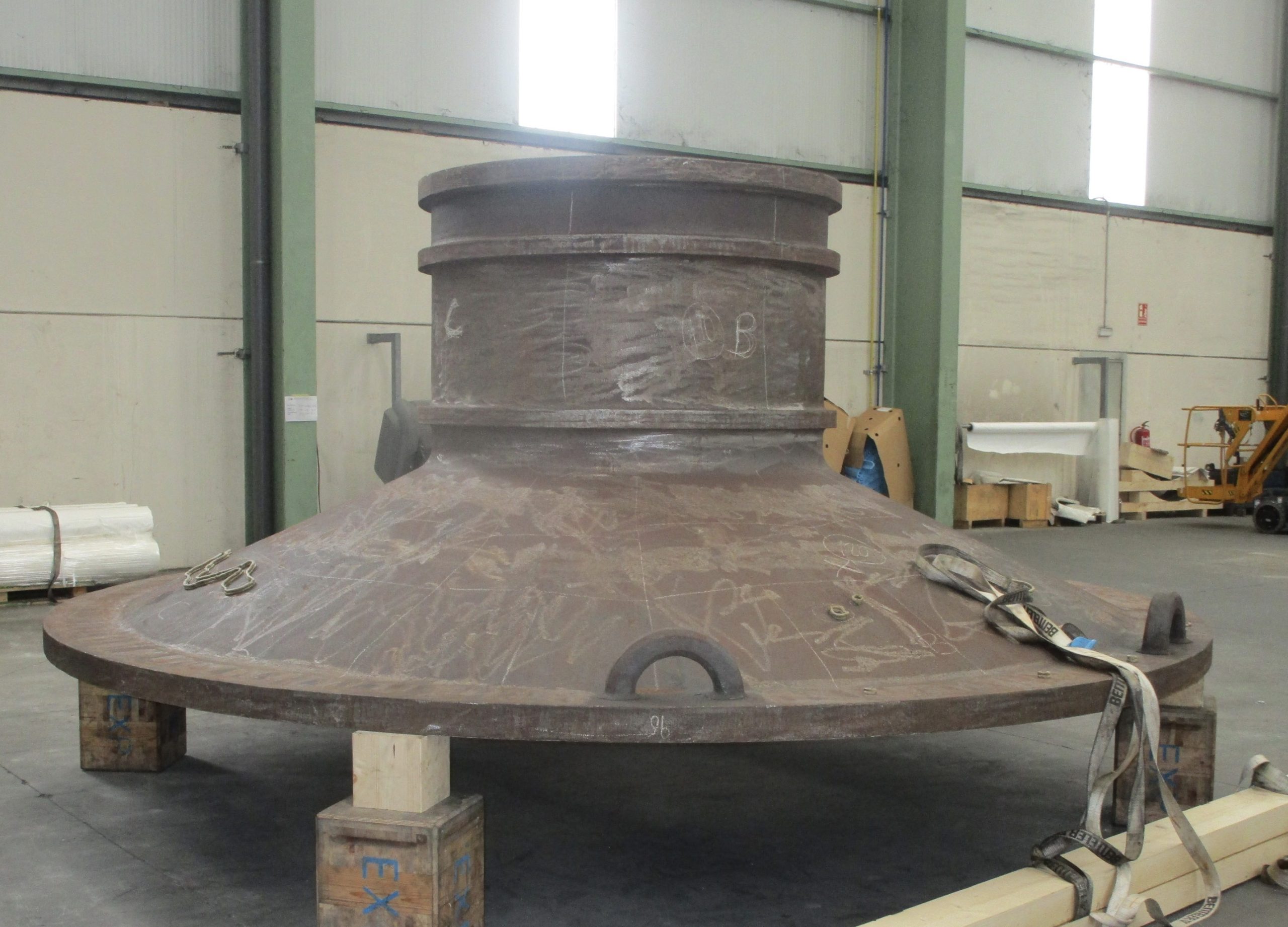
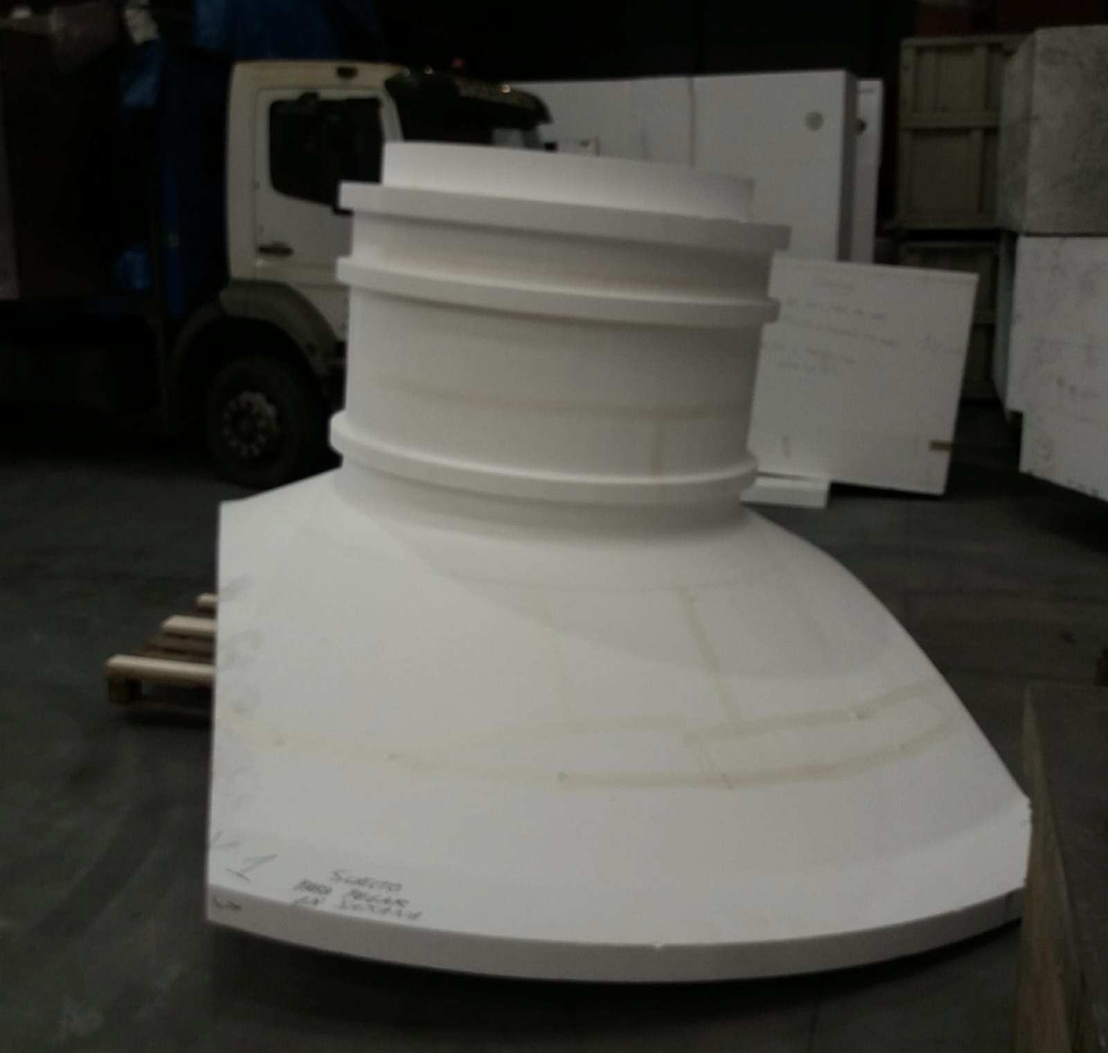
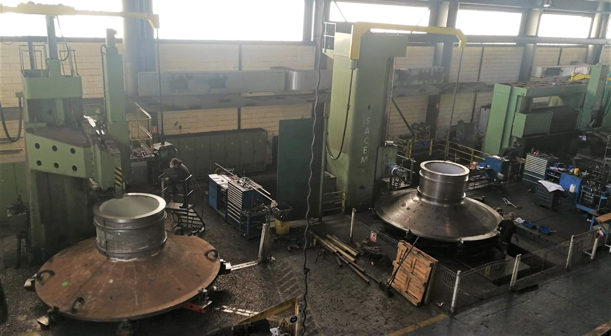
Rough Machining
The focus is on the initial rough machining of the mill covers. This involves removing excess material from the cast component to achieve a shape that is closer to the final dimensions. The rough machining process is critical as it prepares the mill covers for subsequent, more precise machining operations. Key aspects of this phase include:
- Material Removal: Using heavy-duty machining tools to remove large amounts of material efficiently.
- Dimensional Accuracy: Ensuring the machined surfaces meet the required tolerances for the next stages of machining.
- Surface Quality: Achieving a surface finish that is suitable for further machining and processing.
- Inspection: Conducting preliminary inspections to verify that the rough machining process has been performed correctly and the component meets initial specifications.
This phase sets the foundation for the final machining stages, ensuring that the mill covers are accurately shaped and ready for precise finishing operations.
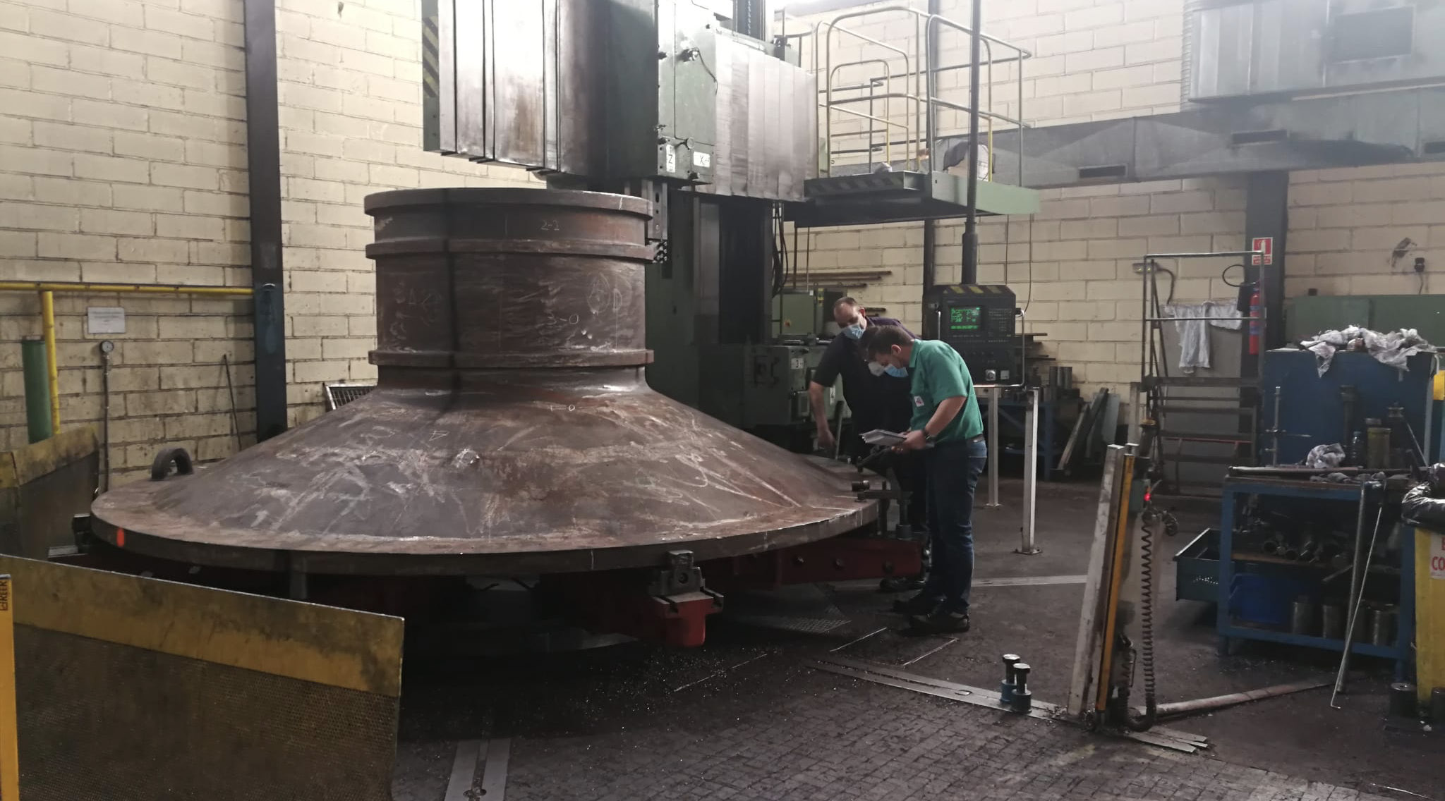
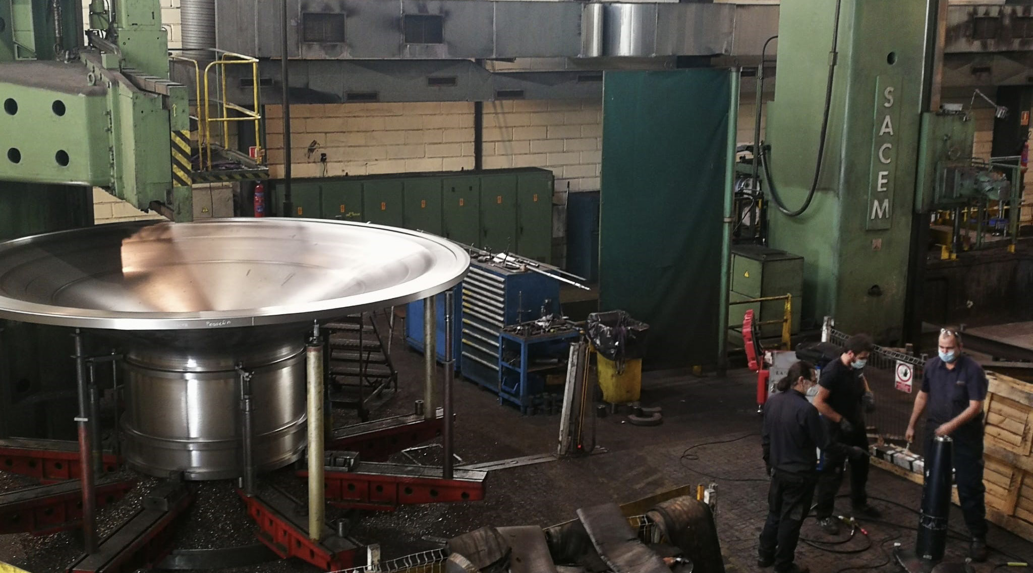
Finishing Machining
This involves precision machining to achieve the final dimensions, tolerances, and surface quality required for the component. The finishing machining process is crucial as it ensures that the mill covers meet all the necessary specifications for optimal performance. Key aspects of this phase include:
- Precision Machining: Using advanced machining tools and techniques to achieve the exact dimensions and tight tolerances specified in the design.
- Surface Finish: Achieving a high-quality surface finish that meets the required standards for smoothness and functionality.
- Final Inspection: Conducting thorough inspections to verify that all dimensions, tolerances, and surface finishes are within specified limits.
- Quality Assurance: Ensuring that the final product meets all industry standards and customer requirements through rigorous quality control processes.
This phase ensures that the mill covers are ready for installation and operation, providing reliability and efficiency in their intended application.
Dimensional Control with Laser Trackers
LASER TRACKERS Integrated into Casting and Machining Processes
In this phase of the project, the focus is on ensuring precise dimensional control of the mill covers using advanced LASER TRACKER technology. This involves integrating LASER TRACKERS into both the casting and machining processes to achieve high accuracy and consistency in the final product. Key aspects of this phase include:
- Casting Process Integration: Using LASER TRACKERS to monitor and verify the dimensions of the cast components, ensuring they meet initial specifications before machining.
- Machining Process Integration: Employing LASER TRACKERS during the machining process to continually check and adjust the dimensions, ensuring precision at every stage.
- Real-Time Monitoring: Providing real-time feedback during both casting and machining to identify and correct any deviations immediately, preventing costly rework.
- Dimensional Verification: Conducting final dimensional inspections with LASER TRACKERS to ensure the finished mill covers meet all design specifications and tolerances.
- Quality Assurance: Enhancing overall quality control by integrating LASER TRACKERS into the workflow, ensuring each mill cover meets the highest standards of precision and reliability.
This integration of LASER TRACKER technology into the casting and machining processes ensures that the mill covers are manufactured with exceptional accuracy, enhancing their performance and longevity in their operational environment.
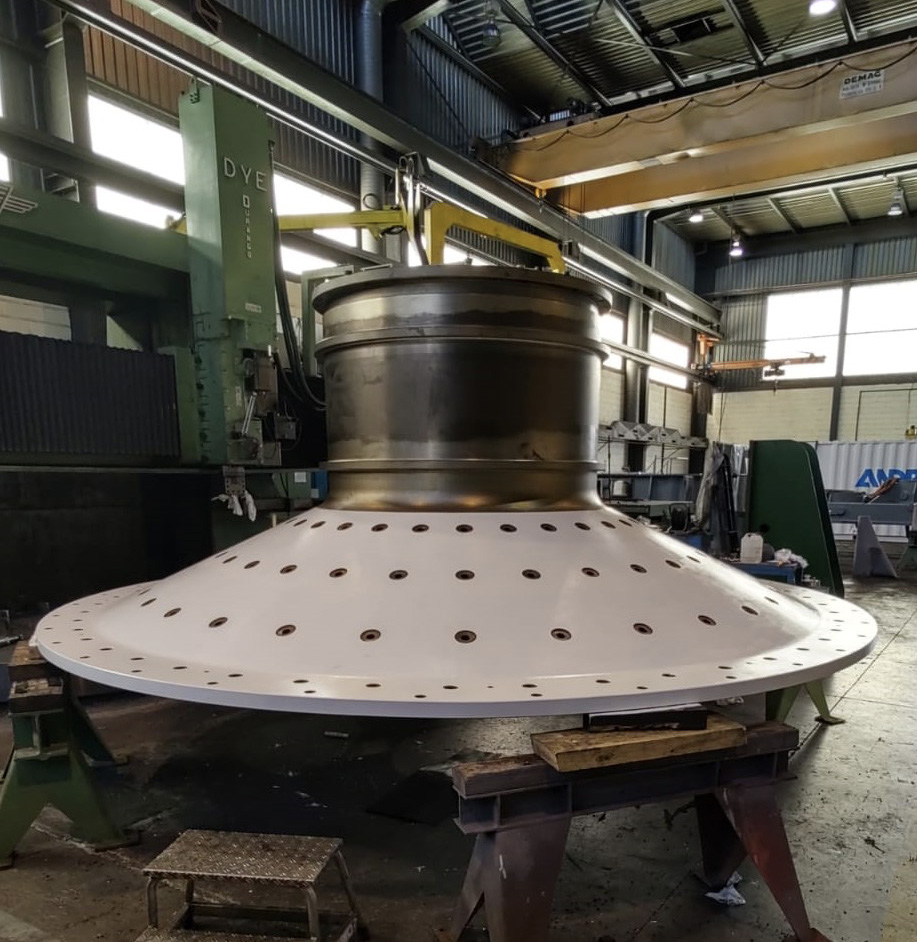
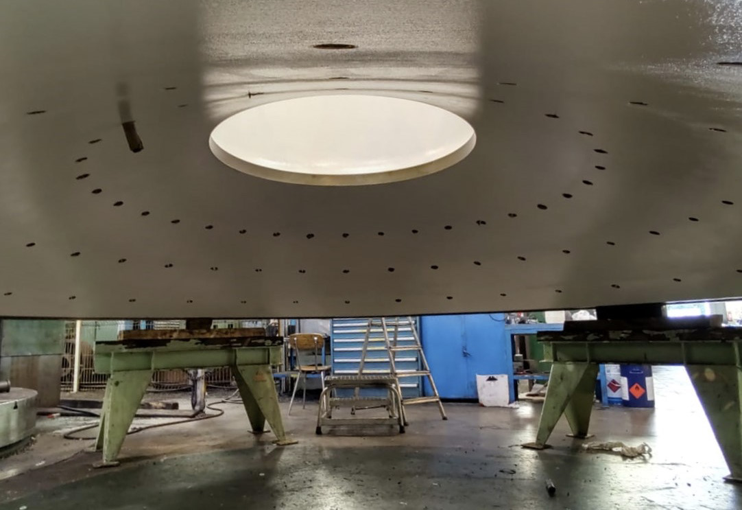
Surface Treatment
This involves a series of processes to prepare and protect the surface, ensuring durability and optimal performance. Key aspects of this phase include:
- Sandblasting: Using high-pressure air and abrasive materials to clean and smooth the surface of the mill covers, removing impurities, rust, and scale.
- Priming: Applying a primer to the sandblasted surface to enhance adhesion and provide additional corrosion protection.
- Coating: Applying the final protective coating, specialized to meet specific environmental and operational requirements.
- Baking: Curing the applied coating in an oven to ensure proper adhesion and achieve the desired hardness and durability.
- Coating Thickness Control: Measuring the thickness of the applied coating to ensure it meets specified standards.
- Adhesion Analysis: Testing the adhesion of the coating to ensure it is firmly attached and will not peel or flake off.
- Quality Inspection: Conducting thorough inspections after each step to verify that the surface treatment has been applied effectively and meets all standards.
This comprehensive surface treatment process ensures that the mill covers are functional and protected against various operational and environmental challenges, extending their service life and maintaining their performance.
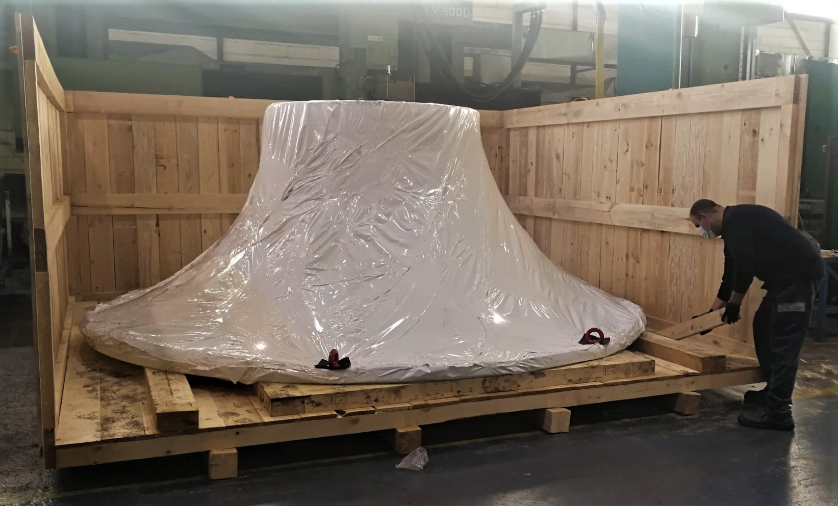
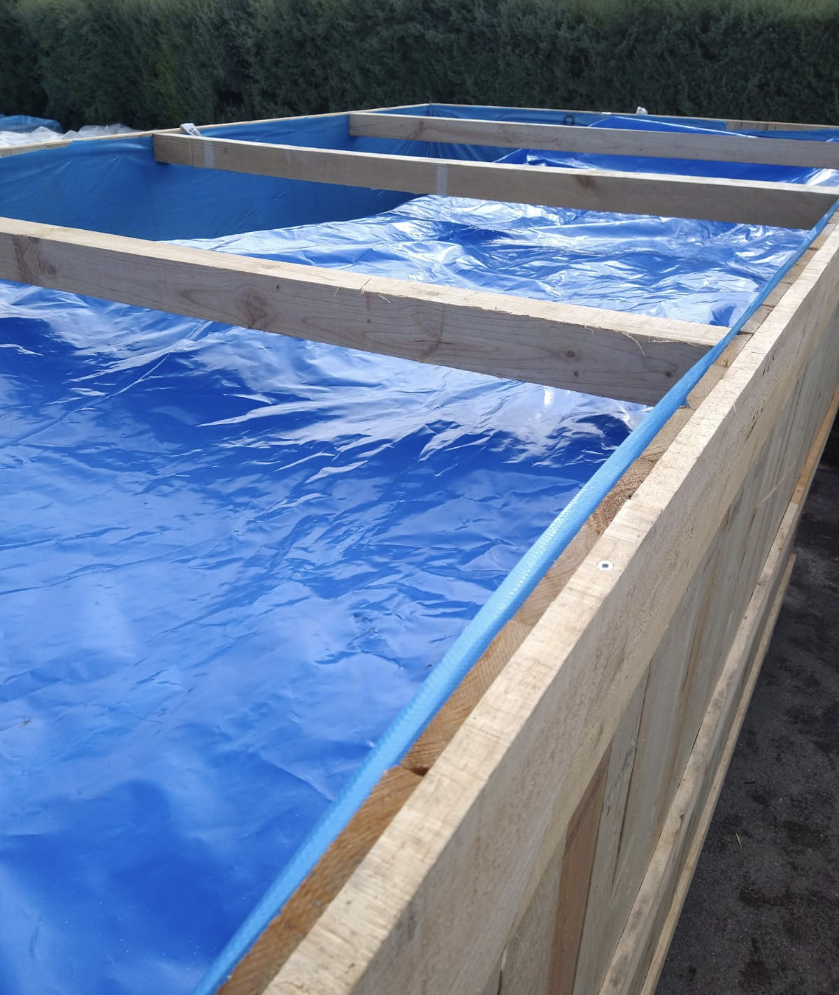
Preparation for Maritime Shipping
In this phase, the focus is on preparing the mill covers for safe and secure maritime shipping. This includes cleaning and inspecting the covers, protective packaging to prevent damage, crating and palletizing for stability, and using moisture control methods. Proper labeling, documentation, and careful loading into shipping containers are also essential to ensure the components arrive at their destination in optimal condition.
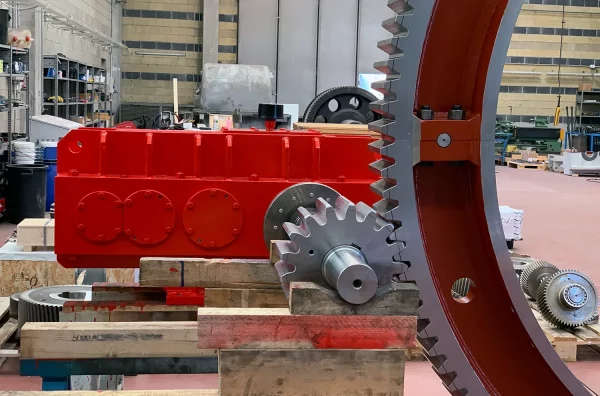
ABS and ACB, Technical Excellence for the Cement Industry
For over 20 years, ABS and ACB has been providing innovative products and engineering solutions for a wide range of industrial applications, including Mill Heads, Ball Mills, Rotary Dryer Furnaces, and Bucket Elevators. Our gearboxes and components are designed to adapt to any assembly requirement, space availability, and required torque and ratio.
We offer a comprehensive range of special bearings and power transmission solutions specifically for the CEMENT and MINING industry, aimed at optimizing your production processes and extending the lifespan of your industrial equipment. At ABS, we are committed to delivering high-quality, reliable solutions to meet your unique needs and ensure the success of your operations.
Download on PDF presentation!